Equilibrium definition and problem answer

Equilibrium definition and problem answer

problem :- Determine the values of the reactions of RA and RB for the simply-supported beam shown
Equilibrium definition and problem anshwer
Also red:- Problem 1.2 : Determine the values of the reactions RA and RB, when a beam is simplysupported at its ends and subjected to a downward force of 5 kN.
Solution:
Taking moments about B
clockwise couples = counter-clockwise couples
RA x 4 = 3 x 6+10 x2
RA = 18 + 20/4
RA = 9.5 kN
Resolving forces vertically
RA+RB = 3+10
Or
RB = 13 - 9.5 = 3.5 kN

Equilibrium definition and problem anshwer

Equilibrium definition and problem answer

This section will be limited to one- or two-dimensional systems, where all the forces and couples will be acting in on plane; such a system of forces is called a coplanar system. In two dimensions, equilibrium is acheved when the following laws are satisfied:

upward forces = downward forces.
forces to the left = forces to the right. 
clockwise couples = counter-clockwise couples.

 To demonstrate the use of these two-dimensional laws of equilibrium, the following problems will be considered.

Also read:- FLOW MEASURING DEVICES
Equilibrium definition and problem answer
Problem 1.2 : Determine the values of the reactions RA and RB, when a beam is simplysupported at its ends and subjected to a downward force of 5 kN.

Solution:
For this problem, it will be necessary to take moments. By taking moments, it is meant that the values of the moments must be considered about a suitable position. Suitable positions for takmg moments on this beam are A and B. This is because, if moments are taken about A, the unknown section RA will have no lever and hence, no moment about A, thereby simplifying the arithmetic. Similarly, by talung moments about B, the unknown RE will have no lever and hence, no moment about B, thereby simplifying the arithmetic. Taking moments about B.
clockwise moments = counter-clockwise moments
RAx(4+2) = 5x2
Or
RA = 10/6
RA = 1.667 kN
Resolving forces vertically upward forces = downward forces

RA+RB = 5
Or
RB = 5 - RA = 5 - 1.667
RA = 3.333kN Answer.

FLOW MEASURING DEVICES

FLOW MEASURING DEVICES

Venturi Tube

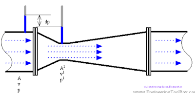
Due to simplicity and dependability, the Venturi tube flowmeter is often used in applications where it's necessary with higher Turn down rates, or lower pressure drops, than the orifice plate can provide. In the Venturi Tube the fluid flowrate is measured by reducing the cross sectional flow area in the flow path, generating a pressure difference. After the constricted area, the fluid is passes through a pressure recovery exit section, where up to 80% of the differential pressure generated at the constricted area, is recovered.
vanturi meter

uses

With proper instrumentation and flow calibrating, the Venturi Tube flowrate can be reduced to about 10% of its full scale range with proper accuracy. This provides a turndown rate 10:1. Orifice, nozzle and Ventury meter.

Rotameter

The rotameter consists of a vertically oriented glass (or plastic) tube with a larger end at the top, and a metering float which is free to move within the tube. Fluid flow causes the float to rise in the tube as the upward pressure differential and buoyancy of the fluid overcome the effect of gravity. The float rises until the annular area between the float and tube increases sufficiently to allow a state of dynamic equilibrium between the upward differential pressure and buoyancy factors, and downward gravity factors. The height of the float is an indication of the flow rate. The tube can be calibrated and graduated in appropriate flow units.
The rotameter consists of a vertically oriented glass (or plastic) tube with a larger end at the top, and a metering float which is free to move within the tube. Fluid flow causes the float to rise in the tube as the upward pressure differential and buoyancy of the fluid overcome the effect of gravity.
Rotamitre

Uses

The rotameter meter typically have a TurnDown Ratio up to 12:1. The accuracy may be as good as 1% of full scale rating. Magnetic floats can be used for alarm and signal transmission functions.

Pitot Tube

The pitot tube are one the most used (and cheapest) ways to measure fluid flow, especially in air applications like ventilation and HVAC systems, even used in airplanes for speed measurent. The pitot tube measures the fluid flow velocity by converting the kinetic energy of the flow into potential energy. The use of the pitot tube is restricted to point measuring. With the "annubar", or multi-orifice pitot probe, the dynamic pressure can be measured across the velocity profile, and the annubar obtains an averaging effect.

Vortex flow meter

Principle of Vortex flowmeter - An introduction to the vortex flowmeter principle. • An obstruction in a fluid flow creates vortices in a downstream flow. Every obstruction has a critical fluid flow speed at which vortex shedding occurs. Vortex shedding is the instance where alternating low pressure zones are generated in the downstream.
Principle of Vortex flowmeter - An introduction to the vortex flowmeter principle. • An obstruction in a fluid flow creates vortices in a downstream flow. Every obstruction has a critical fluid flow speed at which vortex shedding occurs.
vortex flow meter

uses

These alternating low pressure zones cause the obstruction to move towards the low pressure zone. With sensors gauging the vortices the strength of the flow can be measured.

Calorimetric Flowmeter

The calorimetric principle for fluid flow measurement is based on two temperature sensors in close contact with the fluid but thermal insulated from each other. One of the two sensors is constantly heated and the cooling effect of the flowing fluid is used to monitor the flowrate. In a stationary (no flow) fluid condition there is a constant temperature difference between the two temperature sensors. When the fluid flow increases, heat energy is drawn from the heated sensor and the temperature difference between the sensors are reduced. The reduction is proportional to the flow rate of the fluid.
The calorimetric principle for fluid flow measurement is based on two temperature sensors in close contact with the fluid but thermal insulated from each other.
calorimetric flowmeter

uses

Response times will vary due the thermal conductivity of the fluid. In general lower thermal conductivity require higher velocity for proper measurement. The calorimetric flowmeter can achieve relatively high accuracy at low flow rates.


FLOW MEASURING DEVICES

Weirs

Weirs are structures consisting of an obstruction such as a dam or bulkhead placed across the open channel with a specially shaped opening or notch. The flow rate over a weir is a function of the head on the weir. Common weir constructions are the rectangular weir, the triangular or v-notch weir, and the broad-crested weir. Weirs are called sharp-crested if their crests are constructed of thin metal plates, and broad-crested if they are made of wide timber or concrete.
Weirs are structures consisting of an obstruction such as a dam or bulkhead placed across the open channel with a specially shaped opening or notch.
weirs

Orifice Plate

With an orifice plate, the fluid flow is measured through the difference in pressure from the upstream side to the downstream side of a partially obstructed pipe. The plate obstructing the flow offers a precisely measured obstruction that narrows the pipe and forces the flowing fluid to constrict. The orifice plates are simple, cheap and can be delivered for almost any application in any material.
With an orifice plate, the fluid flow is measured through the difference in pressure from the upstream side to the downstream side of a partially obstructed pipe.
orifice plate

uses

The Turndown rates for orifice plates are less than 5:1. Their accuracy are poor at low flow rates. A high accuracy depend on an orifice plate in good shape, with a sharp edge to the upstream side. Wear reduces the accuracy. Orifice, Nozzle and Ventury meter.

Railway engineering for diploma and ssc

RAILWAY ENGINEERING

Railway engineering from transportation engineering
Railway engineering for transportation engineering

Role of railways in transportation

E
conomic aspects Cultural and Social aspects Political aspects

Economical aspects :-

Due to railways, the industrial development in for off places is possible, increasing the land values & standard of living of the people.
Also read :-plane table survey | easy to remember
Mobility of labour has contributed to industrial development. During famines, railways have played the vital role in transporting food & clothing to the affected areas. Commercial farming is very much helped by the railway network throughout the country. Speed movement of the commodities is possible through railways.
Railway engineering for transportation engineering

Cultural & Social aspects :- Cultural & Social aspects :-

Railway has made it easier to reach places of religious importance. Railway provide a convenient & safe mode of transport through out the country. During travel as people of different caste & religions sit together the interaction is developed.

Political aspects :-

Railway have helped in the mass migration of the population. Railway have created the sense of unity among the people of different religions, areas, castes & traditions. With adequate network of railways, the central administration has become easy & effective.
Railway engineering for transportation engineering

History of Railways in India

1832 :- First proposal for a railway in India, in between Madras(Now Chennai) & Bangalore. This remained a dream on paper. 1844 :- First proposal for the construction of railways, in India were submitted to East India company by Mr. R.Macdonald Stephenson. 1849 :- The construction of first experimental line of 160 kms from Calcutta to Mirzapur was undertaken by East India company. 1850 :- Contract to cons • 1853:- The first train in India was run at 3:30 PM on 16th April 1853, between Bombay & Thana. It carried about 400 people in 14 coaches & was driven by 3 engines. 1854:- On August 15th , the first passenger train in the Eastern railway section is operated, from Howarah to Hoogly (39kms). 1856 :- On July 1 st , the first train in the South railway was operated from Royapuram/(Madras) to Wallajah road (approx 100 kms) by the madras railway company. 1859 :- On March 3 rd , the first train in North railway was operated, from Allahabad to Kanpur (180kms). 1862 :- Feb-8 , Jamaipur Loco works establishes. 1864:- August 1 st , first train into Delhi. 1865:- Yamuna Bridge at Allahabad opened. 1869 :- Total track age in India is about 400 miles. 1870 :- Connectivity between Bombay & Calcutta. Mobile Post office services in train. 1879 :- India had a total of 14,920 kms of railway line. 1888 :- Construction of Bombay Victoria Terminus building is completed. Indian standard time (IST) comes into force for timekeeping in British India. 1905 :- Railway Board was established & Board is under the department of Commerce & Industry. 1915:- First over diesel locomotive in India. 1921:- The total length of line laid in India was 58,776kms. • 1922 :-The railway board was reorganized. • 1923 :- Nationalization of railway started. • 1936 :- Air conditioning Introduced in some (first class) passenger coaches. • 1937 :- Burma was separated from India curtailing 3200 km line. 1942 :- Second world war ‘Military Transport Board’ was formed & for the movement of military line up to various strategic points. • 1949-50 :- During that time most of the railway companies were acquired by the government. After Independence the following zonal grouping of railways was done in India.

Railway zones and headquarters

Railway engineering for transportation engineering
Note:- It has recently been decided for better administration & management of Indian railways to set up following 16– new zones.(since from 2003)

Salient Features

Railway cover 63, 327 route Kms as on 2009
Railway engineering for transportation engineering

Production Units:

Railway engineering for transportation engineering

RAILWAY TRACK (PERMANENT WAY)

Definition :- The combination of rails, fitted on sleepers and resting on ballast & sub grade is called the railway track.
Railway engineering for transportation engineering

Permanent way

• In a permanent way, the rails joined in series by fish plates & bolts and then they are fixed to sleepers by different types of fastenings. The sleepers properly spaced & boxed with ballast. • The layers of ballast rest on the prepared sub grade called the formation.
Railway engineering for transportation engineering

Fish Plates

Railway engineering for transportation engineering

sleepers of railway

Railway engineering for transportation engineering

Gauges

Definition :- It is the clear distance between two parallel rails laid.
Railway engineering for transportation engineering

Gauges – Types

Standard Gauge -- UK, USA, Canada, Turkey, China 1435 mm (62%). Broad Gauge -- India, Pakistan, Srilanka, Brazil, 1676 /1524 mm (15%) Argentina, Russia Cape Gauge -- Africa, Japan, Australia, 1067 mm (8%) New Zealand Meter Gauge -- India, France, Argentina, 1000 mm (9%) Switzerland Other 23 in no’s -- Other countries

Gauges – In India

Broad Gauge (B.G) --- 1676 mm , 63% Route km. Meter Gauge (M.G) --- 1000 mm, 31% Route km. Narrow Gauge (N.G) --- 763 mm / 610 mm , 06% Route km.

Requirement of an ideal Permanent way

Requirement of an ideal permanent way so as to achieve high speed & better riding qualities with less future maintenance. The gauge should be correct & uniform. The rails should be in proper level. In a straight track, two rails must be at the same level. The alignment should be correct, i.e should be free from kinks or irregularities. The gradient should be uniform & as gentle as possible. There should be adequate provisions for easy renewals & replacement The track should be resilient & elastic in order to absorb shocks & vibrations of running track. The radii & super elevation on curves should be properly designed & maintained. Drainage system must be perfect for enhancing safety & durability of track. The various components of the track, i.e the rails, fittings, sleepers, ballast& formation must fully satisfy the requirements for which they have been provided. The track structure should be strong, low in initial cost as well as ,maintenance cost

Selection of Gauges

1) Cost of construction :-

• Land, components & earth work : Proportional Increases. • Bridges etc : Marginal Increases. • Buildings, Signals etc : No Increase.

2) Physical features of country:-

• Gradients • Curves Narrow gauge is more suited to the above conditions. Eg:- Hill Railways :- Kalka – Shimla; Darjeeling ; Uttakmund (Ooty).

Coning of wheels

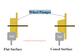
The distance between the inside edges of wheel flanges is generally kept less than the gauge of the track. So there is a gap between the wheel flanges and running edges of the rails, nearly equal to 1 cm (3/8”) on either side. Normally the tread of wheels is absolutely dead center of the head of the rail, as the wheel is coned to keep it in this central position automatically. These wheels are coned at a slope of 1 in 20.
Railway engineering for transportation engineering

Wheel Flanges

Railway engineering for transportation engineering
There are two types Flat Surface Unequal moment on curved rails

Problems with flat wheel

Lateral sway on straight track, wearing of flanges & side of rail head.

Unequal moment on curved rails

Longer distance to be moved on outer curved rails as compared to inner curved rail.
Railway engineering for transportation engineering

Advantages of coning of wheels

To reduce the wear & tear of the wheel flanges & rails, which is due to rubbing action of flanges with inside faces of the rail head. To provide a possibility of lateral movement of the axle with its wheels. To provide the wheels from slipping to some extent. Smooth riding.

Disadvantages of coning of wheels

Pressure on outer rail is more while on inner rail it is less. This results in wear of outer rail. If no base plate is used under the voids sleepers under the edge of the rail are damaged.

Theodolite full guide

THEODOLITE SURVEYING

The system of surveying in which the angles are measured with the help of a theodolite, is called Theodolite surveying.

HISTORY

Early history People have been measuring angles for construction purposes for many centuries. Egyptians used groma, an early version of a theodolite, to help build the pyramids. Furthermore, there are also records that indicate that the Romans used tools such as dioptra (circular plate that marked angles), for similar purposes. In 1571, Leonard Digges came up with a device which more closely resembled an early theodolite and called it theodolitus. It was a divided circle and square with a compass in the center, according to "Brief History of Turning Angles" at noaa.gov, but it lacked a telescope (found in modern versions).

THEODOLITE

The Theodolite is a most accurate surveying instrument mainly used for:- Measuring horizontal and vertical angles. Locating points on a line. Prolonging survey lines. Finding difference of level. Setting out grades. Ranging curves. Tacheometric Survey.

THEODOLITE

Theodolite full guide
theodolite
Theodolite full guide
teodoloite
Theodolite full guide
electronic theodolite

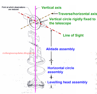
Three assemblies of Theodolite


Theodolite full guide
assemblies of theodolite


Main parts-1 of a theodolite

Theodolite full guide
parts of theodolite

Levelling head

Levelling head is used to attach the instrument to tripod and attach the plumb bob along the vertical axis of the instrument.

Also read :-  75 CIVIL ENGINEERING INTERVIEW QUESTIONS

MAIN PARTS-2 of theodolite


Lower plate/circle plate

an annular horizontal plate with the graduations provided all around, from 0 to 360°, in a clockwise direction. The graduations are in degree divided in to 3 parts so that each division equals to 20 min. Horizontal angles are measured with this plate. The size of the theodolite is defined by the diameter of horizontal circle. Upper plate (17): Horizontal plate of smaller diameter provided with two verniers. on diametrically opposite parts of its circumference. These verniers are designated as A and B. They are used to read fractions of the horizontal circle plate graduations. The verniers are graduated in 20 min and each minute is divided in 3 to 5 parts making least count 20” or 10”.

MAIN PARTS-3 of theodolite


Clamps and tangent screws

There are two clamps and associated tangent screws with the plate. These screws facilitate the motion of the instruments in horizontal plane. Lower clamp screw locks or releases the lower plate. When this screw is unlocked both upper and lower plates move together. The associated lower tangent screw allows small motion of the plate in locked position. The upper clamp screw locks or releases the upper vernier plate. When this clamp is released the lower plate does not move but the upper vernier plate moves with the instrument. This causes the change in the reading. The upper tangent screw allows the fine adjustment.

MAIN PARTS-4 of theodolite

Plate level of theodolite

Spirit level with the bubble and graduation on glass cover. A single level or two levels fixed in perpendicular direction may be provided. The spirit level can be adjusted with the foot screw (21) of the levelling head (7).

Telescope of theodolite

The essential parts of the telescopes are eye-piece, diaphragm with cross hairs, object lens and arrangements to focus the telescope.

MAIN PARTS-5 of theodolite

Vertical circle of theodolite

circular plate supported on horizontal axis of the instrument between the A-frames. Vertical circle has graduation 0-90 in four quadrants. Vertical circle moves with the telescope when it is rotated in the vertical plane. Vertical circle clamp and tangent screw Clamping the vertical circle restrict the movement of telescope in vertical plane.

Altitude level of theodolite

A highly sensitive bubble is used for levelling particularly when taking the vertical angle observations.
Theodolite full guide
altitude level

Reading a theodolite

Theodolite full guide
reading a theodolite

TERMS USED IN MANIPULATING A TRANSIT VERNIER THEODOLITE.

Centering of theodolite

Centering means setting the theodolite exactly over an instrument- station so that its vertical axis lies immediately above the station- mark. It can be done by means of plumb bob suspended from a small hook attached to the vertical axis of the theodolite. The centre shifting arrangement if provided with the instrument helps in easy and rapid performance of the centring.

Transiting of theodolite

Transiting is also known as plunging or reversing. It is the process of turning the telescope about its horizontal axis through 1800 in the vertical plane thus bringing it upside down and making it point , exactly in opposite direction.

Swinging the telescope of theodolite

It means turning the telescope about its vertical axis in the horizontal plane. A swing is called right or left according as the telescope is rotated clockwise or counter clockwise.

Face Left of theodolite

If the vertical circle of the instrument is on the left side of the observer while taking a reading ,the position is called the face left and the observation taken on the horizontal or vertical circle in this position, is known as the face left observation

Face Right of theodolite

If the vertical circle of the instrument is on the right side of the observer while taking a reading ,the position is called the face right and the observation taken on the horizontal or vertical circle in this position, is known as the face right observation.

Changing Face of theodolite

It is the operation of bringing the vertical circle to the right of the observer ,if originally it is to the left , and vice – versa. It is done in two steps; Firstly revolve the telescope through 1800 in a vertical plane and then rotate it through 1800 in the horizontal plane i.e first transit the telescope and then swing it through 1800 .

Line of Collimation of theodolite


line of collimation of theodolite
It is also known as the line of sight .It is an imaginary line joining the intersection of the cross- hairs of the diaphragm to the optical centre of the object- glass and its continuation.

Axis of the telescope

Theodolite full guide
It is also known an imaginary line joining the optical centre of the object- glass to the centre of eye piece.

Axis of the Level Tube

It is also called the bubble line. It is a straight line tangential to the longitudinal curve of the level tube at the centre of the tube. It is horizontal when the bubble is in the centre.

Vertical Axis

It is the axis about which the telescope can be rotated in the horizontal plane.

Horizontal Axis

It is the axis about which the telescope can be rotated in the vertical plane. It is also called the trunion axis.

ADJUSTMENT OF A THEODOLITE

The adjustments of a theodolite are of two kinds :- 1. Permanent Adjustments. 2. Temporary Adjustments.

Permanent adjustments

The permanent adjustments are made to establish the relationship between the fundamental lines of the theodolite and , once made , they last for a long time. They are essential for the accuracy of observations. The permanent adjustments in case of a transit theodolites are :- Adjustment of Horizontal Plate Levels. The axis of the plate levels must be perpendicular to the vertical axis. Collimation Adjustment. The line of collimation should coincide with the axis of the telescope and the axis of the objective slide and should be at right angles to the horizontal axis. Horizontal axis adjustment. The horizontal axis must be perpendicular to the vertical axis. Adjustment of Telescope Level or the Altitude Level Plate Levels. The axis of the telescope levels or the altitude level must be parallel to the line of collimation. Vertical Circle Index Adjustment. The vertical circle vernier must read zero when the line of collimation is horizontal.

Temporary Adjustment

The temporary adjustments are made at each set up of the instrument before we start taking observations with the instrument. There are three temporary adjustments of a theodolite:- Centering. Levelling. Focussing.

Measurement of horizontal angle of theodolite

Theodolite full guide
measure horizontal angle
Measurement of Angle ABC The instrument is set over B. The lower clamp is kept fixed and upper clamp is loosened. Turn the telescope clockwise set vernier A to 0° and vernier B to approximately 180°. Upper clamp is tightened and using the upper tangent screw the vernier A and B are exactly set to 0° and 180°. Upper clamp is tightly fixed, lower one is loosened and telescope is directed towards A and bisect the ranging rod at A. Tightened the lower clamp and turn the lower tangent screw to perfectly bisect ranging rod at A. Loose the upper clamp and turn the telescope clockwise to bisect the ranging rod at C tightened the upper clamp and do the fine adjustment with upper tangent screw. The reading on vernier A and B are noted. Vernier A gives the angle directly and vernier B gives the reading by subtracting the initial reading (180°) from final reading. Read these two method Repetition method Reiteration method

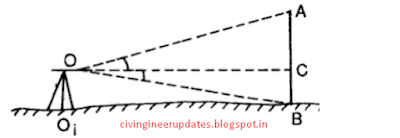
Vertical angle measurement-1

Theodolite full guide
vertical angle measurment

Vertical angle measurement

There are two methods of prolonging a given line such as AB (1) Fore sight method (2) Back Sight Method

Fore Sight Method. As shown in the fig. below

Theodolite full guide
vertical angle measurment 
(a).Set up the theodolite at A and level it accurately .Bisect the point b correctly. Establish a point C in the line beyond B approximately by looking over the top of the telescope and accurately by sighting through the telescope. (b).Shift the instrument to B ,take a fore sight on C and establish a point D in line beyond C. Repeat the process until the last point Z is reached.

Back Sight Method.

Theodolite full guide
back sight method
Set up the instrument at B and level it accurately . (a).Take a back sight on A. (b). Tighten the upper and lower clamps, transit the telescope and establish a point C in the line beyond B. (c).Shift the theodolite to C ,back sight on B transit the telescope and establish a point D in line beyond C. Repeat the process until the last point ( Z) is established. Now if the instrument is in adjustment, the points A,B,C,D and Z will be in one line, which is straight but if it is not in adjustment i.e. line of collimation is not perpendicular to the horizontal axis ,then C’, D’ and Z’ will not be in a straight line.

75 CIVIL ENGINEERING INTERVIEW QUESTIONS

 75 CIVIL ENGINEERING INTERVIEW QUESTIONS
source this image:- https://www.facebook.com/groups/1920094914972262/


1. What is the bending moment (BM) & Shear force (SF) – Explain.
2. What are the steps involved in the concreting process, explain?
3. Describe briefly the various methods of concrete curing.
4. What is the minimum curing period?
5. What Do You Understand by M25 Concrete?

mechanics of structures lab | mos 4th sam for civil diploma

I
ntellectual skills:

1.calculate design parameters.

motor skill

1.observe the phenomenon during testing of specimen.
2.draw the graphs and diagrams.

list of practical:

1. identify the componenets of universal testing machine and tension test on mild steel.
2.tension test on steel / deformation bars.
3.izod impact test on mild steel brass copper and cast iron etc.