THEODOLITE SURVEYING
The
system of surveying in which the angles are measured with the help of a
theodolite, is called Theodolite surveying.
HISTORY
Early history
People have been measuring angles for construction purposes for many centuries. Egyptians used groma, an early version of a theodolite, to help build the pyramids. Furthermore, there are also records that indicate that the Romans used tools such as dioptra (circular plate that marked angles), for similar purposes. In 1571, Leonard Digges came up with a device which more closely resembled an early theodolite and called it theodolitus. It was a divided circle and square with a compass in the center, according to "Brief History of Turning Angles" at noaa.gov, but it lacked a telescope (found in modern versions).
THEODOLITE
The Theodolite is a most accurate surveying instrument mainly used for:-
Measuring horizontal and vertical angles.
Locating points on a line.
Prolonging survey lines.
Finding difference of level.
Setting out grades.
Ranging curves.
Tacheometric Survey.
THEODOLITE
 |
| theodolite |
 |
| teodoloite |
 |
| electronic theodolite |
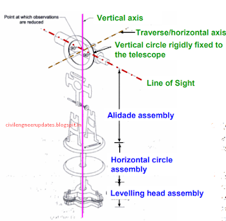
Three assemblies of Theodolite
 |
| assemblies of theodolite |
Main parts-1 of a theodolite
 |
| parts of theodolite |
Levelling head
Levelling head is used to attach the instrument to tripod and attach the plumb bob along the vertical axis of the instrument.
Also read :- 75 CIVIL ENGINEERING INTERVIEW QUESTIONS
MAIN PARTS-2 of theodolite
Lower plate/circle plate
an annular horizontal plate with the graduations provided all around, from 0 to 360°, in a clockwise direction. The graduations are in degree divided in to 3 parts so that each division equals to 20 min. Horizontal angles are measured with this plate. The size of the theodolite is defined by the diameter of horizontal circle. Upper plate (17): Horizontal plate of smaller diameter provided with two verniers. on diametrically opposite parts of its circumference. These verniers are designated as A and B. They are used to read fractions of the horizontal circle plate graduations. The verniers are graduated in 20 min and each minute is divided in 3 to 5 parts making least count 20” or 10”.
MAIN PARTS-3 of theodolite
Clamps and tangent screws
There are two clamps and associated tangent screws with the plate. These screws facilitate the motion of the instruments in horizontal plane. Lower clamp screw locks or releases the lower plate. When this screw is unlocked both upper and lower plates move together. The associated lower tangent screw allows small motion of the plate in locked position. The upper clamp screw locks or releases the upper vernier plate. When this clamp is released the lower plate does not move but the upper vernier plate moves with the instrument. This causes the change in the reading. The upper tangent screw allows the fine adjustment.
MAIN PARTS-4 of theodolite
Plate level of theodolite
Spirit level with the bubble and graduation on glass cover. A single level or two levels fixed in perpendicular direction may be provided. The spirit level can be adjusted with the foot screw (21) of the levelling head (7).
Telescope of theodolite
The essential parts of the telescopes are eye-piece, diaphragm with cross hairs, object lens and arrangements to focus the telescope.
MAIN PARTS-5 of theodolite
Vertical circle of theodolite
circular plate supported on horizontal axis of the instrument between the A-frames. Vertical circle has graduation 0-90 in four quadrants. Vertical circle moves with the telescope when it is rotated in the vertical plane.
Vertical circle clamp and tangent screw Clamping the vertical circle restrict the movement of telescope in vertical plane.
Altitude level of theodolite
A highly sensitive bubble is used for levelling particularly when taking the vertical angle observations.
 |
| altitude level |
Reading a theodolite
 |
| reading a theodolite |
TERMS USED IN MANIPULATING A TRANSIT VERNIER THEODOLITE.
Centering of theodolite
Centering means setting the theodolite exactly over an instrument- station so that its vertical axis lies immediately above the station- mark. It can be done by means of plumb bob suspended from a small hook attached to the vertical axis of the theodolite. The centre shifting arrangement if provided with the instrument helps in easy and rapid performance of the centring.
Transiting of theodolite
Transiting is also known as plunging or reversing. It is the process of turning the telescope about its horizontal axis through 1800 in the vertical plane thus bringing it upside down and making it point , exactly in opposite direction.
Swinging the telescope of theodolite
It means turning the telescope about its vertical axis in the horizontal plane. A swing is called right or left according as the telescope is rotated clockwise or counter clockwise.
Face Left of theodolite
If the vertical circle of the instrument is on the left side of the observer while taking a reading ,the position is called the face left and the observation taken on the horizontal or vertical circle in this position, is known as the face left observation
Face Right of theodolite
If the vertical circle of the instrument is on the right side of the observer while taking a reading ,the position is called the face right and the observation taken on the horizontal or vertical circle in this position, is known as the face right observation.
Changing Face of theodolite
It is the operation of bringing the vertical circle to the right of the observer ,if originally it is to the left , and vice – versa. It is done in two steps; Firstly revolve the telescope through 1800 in a vertical plane and then rotate it through 1800 in the horizontal plane i.e first transit the telescope and then swing it through 1800 .
Line of Collimation of theodolite
 |
| line of collimation of theodolite |
It is also known as the line of sight .It is an imaginary line joining the intersection of the cross- hairs of the diaphragm to the optical centre of the object- glass and its continuation.
Axis of the telescope
It is also known an imaginary line joining the optical centre of the object- glass to the centre of eye piece.
Axis of the Level Tube
It is also called the bubble line. It is a straight line tangential to the longitudinal curve of the level tube at the centre of the tube. It is horizontal when the bubble is in the centre.
Vertical Axis
It is the axis about which the telescope can be rotated in the horizontal plane.
Horizontal Axis
It is the axis about which the telescope can be rotated in the vertical plane. It is also called the trunion axis.
ADJUSTMENT OF A THEODOLITE
The adjustments of a theodolite are of two kinds :-
1. Permanent Adjustments.
2. Temporary Adjustments.
Permanent adjustments
The permanent adjustments are made to establish the relationship between the fundamental lines of the theodolite and , once made , they last for a long time. They are essential for the accuracy of observations.
The permanent adjustments in case of a transit theodolites are :-
Adjustment of Horizontal Plate Levels. The axis of the plate levels must be perpendicular to the vertical axis.
Collimation Adjustment. The line of collimation should coincide with the axis of the telescope and the axis of the objective slide and should be at right angles to the horizontal axis.
Horizontal axis adjustment. The horizontal axis must be perpendicular to the vertical axis.
Adjustment of Telescope Level or the Altitude Level Plate Levels. The axis of the telescope levels or the altitude level must be parallel to the line of collimation.
Vertical Circle Index Adjustment. The vertical circle vernier must read zero when the line of collimation is horizontal.
Temporary Adjustment
The temporary adjustments are made at each set up of the instrument before we start taking observations with the instrument. There are three temporary adjustments of a theodolite:-
Centering.
Levelling.
Focussing.
Measurement of horizontal angle of theodolite
 |
| measure horizontal angle |
Measurement of Angle ABC
The instrument is set over B.
The lower clamp is kept fixed and upper clamp is loosened.
Turn the telescope clockwise set vernier A to 0° and vernier B to approximately 180°.
Upper clamp is tightened and using the upper tangent screw the vernier A and B are exactly set to 0° and 180°.
Upper clamp is tightly fixed, lower one is loosened and telescope is directed towards A and bisect the ranging rod at A.
Tightened the lower clamp and turn the lower tangent screw to perfectly bisect ranging rod at A.
Loose the upper clamp and turn the telescope clockwise to bisect the ranging rod at C tightened the upper clamp and do the fine adjustment with upper tangent screw.
The reading on vernier A and B are noted. Vernier A gives the angle directly and vernier B gives the reading by subtracting the initial reading (180°) from final reading.
Read these two method
Repetition method
Reiteration method
Vertical angle measurement-1
 |
| vertical angle measurment |
Vertical angle measurement
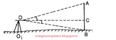
There are two methods of prolonging a given line such as AB
(1) Fore sight method
(2) Back Sight Method
Fore Sight Method. As shown in the fig. below
 |
| vertical angle measurment |
(a).Set up the theodolite at A and level it accurately .Bisect the point b correctly. Establish a point C in the line beyond B approximately by looking over the top of the telescope and accurately by sighting through the telescope.
(b).Shift the instrument to B ,take a fore sight on C and establish a point D in line beyond C.
Repeat the process until the last point Z is reached.
Back Sight Method.
 |
| back sight method |
Set up the instrument at B and level it accurately .
(a).Take a back sight on A.
(b). Tighten the upper and lower clamps, transit the telescope and establish a point C in the line beyond B.
(c).Shift the theodolite to C ,back sight on B transit the telescope and establish a point D in line beyond C. Repeat the process until the last point ( Z) is established.
Now if the instrument is in adjustment, the points A,B,C,D and Z will be in one line, which is straight but if it is not in adjustment i.e. line of collimation is not perpendicular to the horizontal axis ,then C’, D’ and Z’ will not be in a straight line.


2 comments
commentsVery elaborate explanation on Theodolites. While working myself with different survey instruments like Theodolites , alignment telescope , Sight level , Total Station for couple of decades its quite refreshing
ReplyNice blog....Centering Material Manufacturers in Chennai
ReplyScaffolding Material Manufacturers
Wall form manfacturers